The Audio System Diagram Tool is a simple Windows application from HomeGrown Software Development. It is designed to make it easy to create diagrams of your personal home audio setup for use in the Audio System Setups page. The advantages are simplicity and standardization.
Installation
Audio System Diagram Tool
Download the file AudioDiagram_v3.zip and save it to a temporary folder. Unzip the file. The zip should extract to \Program Files\HomeGrown Software\Audio Setup App. There should also be three sub folders; Images, Output and Export. That's it. There are no registry entries and no icons on your desktop.
Simply run the program AudioSetup.exe from explorer or add a shortcut to your Start Menu if you wish.
Overview
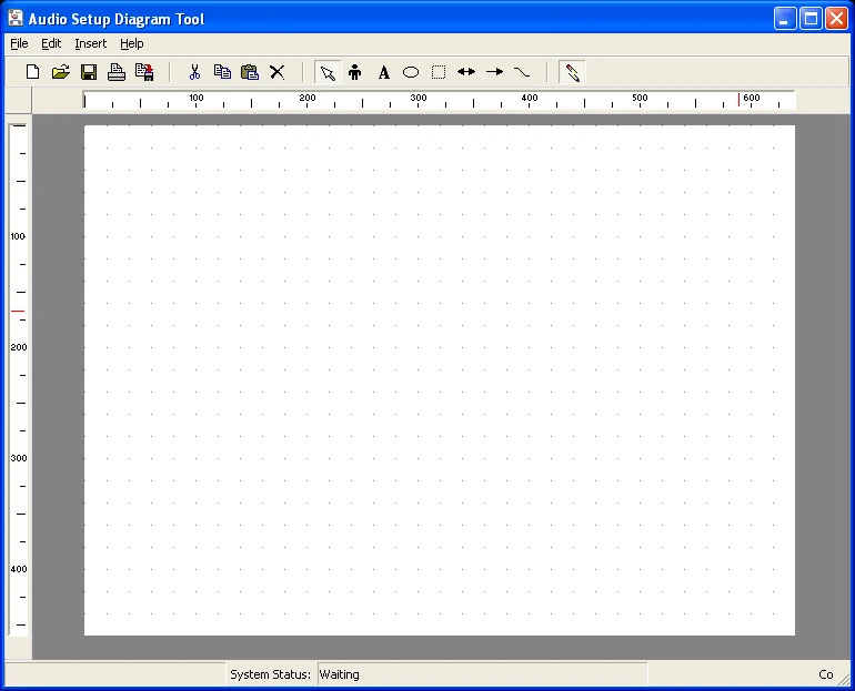
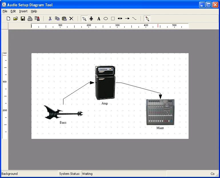
The Audio System Diagram Tool has a blank work surface available when you start it. There is a tool bar above the work surface where you can perform a number of operations such as file save and open, add shapes and graphics and output an image.
There is a status bar below the work surface that will display messages based of the current state of operation. These messages are geared to the inserting and connecting of graphics and shapes.
The application is designed not to be resizable. This way you keep the diagram to a standard size (800x600). On systems with screen resolution below 800x600 the full application will not be visible. Therefore it is not recommended for use with lower resolutions.
Version 2.0.0.0 added the ability to resize the work surface so images of any size can be created.
Add a Graphic
![]()
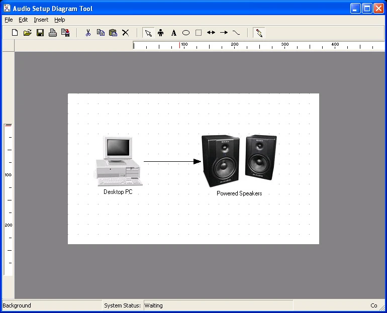
Audio Diagram with some objects
Click on the Add Graphic button, which will stay down, and click anywhere on the work surface. A graphic object will appear where you clicked.
It will be selected by default, that is it will have a selection box drawn around it. Clicking elsewhere on the work surface, or clicking another object if one exists, will de-select it.
Hold the left mouse button down and drag the graphic to any position on the work surface.
Double Click the object to select an image to be displayed in the graphic object. There is a library of images in the \Images\ folder. You can create and use your own images from any program that will create jpegs.
Right Click the object to set the caption to top or bottom of the object.
Add a Shape
![]() Click the Add Shape button, which will stay down, and click anywhere on the work surface. A shape object will appear where you clicked.
Click the Add Shape button, which will stay down, and click anywhere on the work surface. A shape object will appear where you clicked.
It will be selected by default, that is it will have a sizing box drawn around it. Clicking elsewhere on the work surface, or clicking another object if one exists, will de-select it. Dragging on any of the grab handles will re-size the object.
Hold the left mouse button down and drag the shape to any position on the work surface.
Double clicking the shape will cycle through the three available shapes, rectangle, round rectangle and ellipse.
Add Text
![]() Click the Add Text button, which will stay down, and click anywhere on the work surface. A text object will appear where you clicked.
Click the Add Text button, which will stay down, and click anywhere on the work surface. A text object will appear where you clicked.
It will be selected by default, that is it will have a sizing box drawn around it. Clicking elsewhere on the work surface, or clicking another object if one exists, will de-select it. Dragging on any of the sizing spots will re-size the object.
Hold the left mouse button down and drag the text to any position on the work surface.
Double clicking the text object will bring up a dialog where you can enter or edit text and select a font and size. Note that captions for Graphic and Shape objects are Text objects themselves an so double clicking captions gives you the same dialog.
Dragging Objects
Click on one object to select it. If you keep the left mouse button depressed you can drag the object to a new position. Shift-Click multiple objects to select. Holding the shift key down simultaneous with the left mouse button allows you to drag multiple objects.
Delete Selected Object
![]() Select one or more shapes with Shift-Click. Click Ctrl-Delete button to remove selected objects or use the menu item Edit|Delete.
Select one or more shapes with Shift-Click. Click Ctrl-Delete button to remove selected objects or use the menu item Edit|Delete.
Connect Shapes
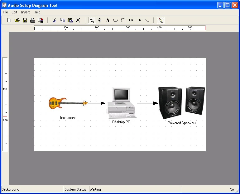
Connected Shapes
Two Way Connection
![]() Click the two-way connection button to join two objects with a double headed arrow to indicate two-way signal transfer (eg: midi). The button will stay down.
Click the two-way connection button to join two objects with a double headed arrow to indicate two-way signal transfer (eg: midi). The button will stay down.
![]() Click the orientation button. To join objects with sides leave this button un-checked. To join objects by top and bottom check this button.
Click the orientation button. To join objects with sides leave this button un-checked. To join objects by top and bottom check this button.
Click the first object to connect, then click the second object. A double headed arrow will be drawn joining the two objects. The order you clicked the objects has no effect here because the arrow indicates two way data transfer.
Version 3 replaced the orientation button and connection logic with a Connection Attributes dialog. This gives you explicit control over the connection points and the connection color.
One Way Connection
![]()
One way connections
Click the one-way connection button to join two objects with a single headed arrow to indicate one-way signal transfer (eg: audio line out). The button will stay down.
![]() Click the orientation button. To join objects with their sides leave this button un-checked. To join objects by top and bottom check this button.
Click the orientation button. To join objects with their sides leave this button un-checked. To join objects by top and bottom check this button.
Click the first object to connect, then click the second object. A single headed arrow will be drawn joining the two objects.
The order you click the objects is important here. If you click the leftmost object first the arrow will be left to right. If you click the rightmost object first the arrow will point right to left.
If the orientation button is checked then if you click the topmost object first the arrow will point top to bottom. If you click the bottom object first the arrow will point bottom to top.
Version 3 replaced the orientation button and connection logic with a Connection Attributes dialog. This gives you explicit control over the connection points and the connection color.
Snap To Grid
The work surface has an invisible grid to which objects can snap to when created or dragged. This feature is designed to make layout easier.
![]() If the SnapToGrid button is depressed the snap to feature is enabled. The default state is enabled. If you wish to disable the feature temporarily simply click the button once. Click again and the snap feature is re-enabled.
If the SnapToGrid button is depressed the snap to feature is enabled. The default state is enabled. If you wish to disable the feature temporarily simply click the button once. Click again and the snap feature is re-enabled.
Version 2 made the snap grid visible by default. The user may toggle the snap grid between visible/invisible using the menu item File|Show Grid. Make sure the grid is not visible during the export of images unless you wish the grid to appear in the output.
File Operations
![]() New. Clears work surface of all objects. No warning to save work so be careful.
New. Clears work surface of all objects. No warning to save work so be careful.
![]() Save. Saves work surface as a binary *.asd file.
Save. Saves work surface as a binary *.asd file.
![]() Open. Open a binary *.asd file. Clears work surface without warning. Loads contents of file to work surface.
Open. Open a binary *.asd file. Clears work surface without warning. Loads contents of file to work surface.
![]() Save as Jpeg. Save work surface as a jpeg file suitable for uploading to this site.
Save as Jpeg. Save work surface as a jpeg file suitable for uploading to this site.